Pre-Installation Checklist
HubSwitch
HubSwitch
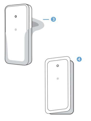
What’s in the Box?
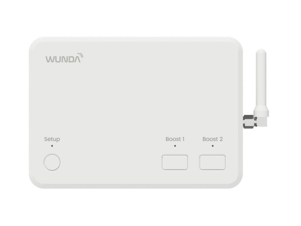
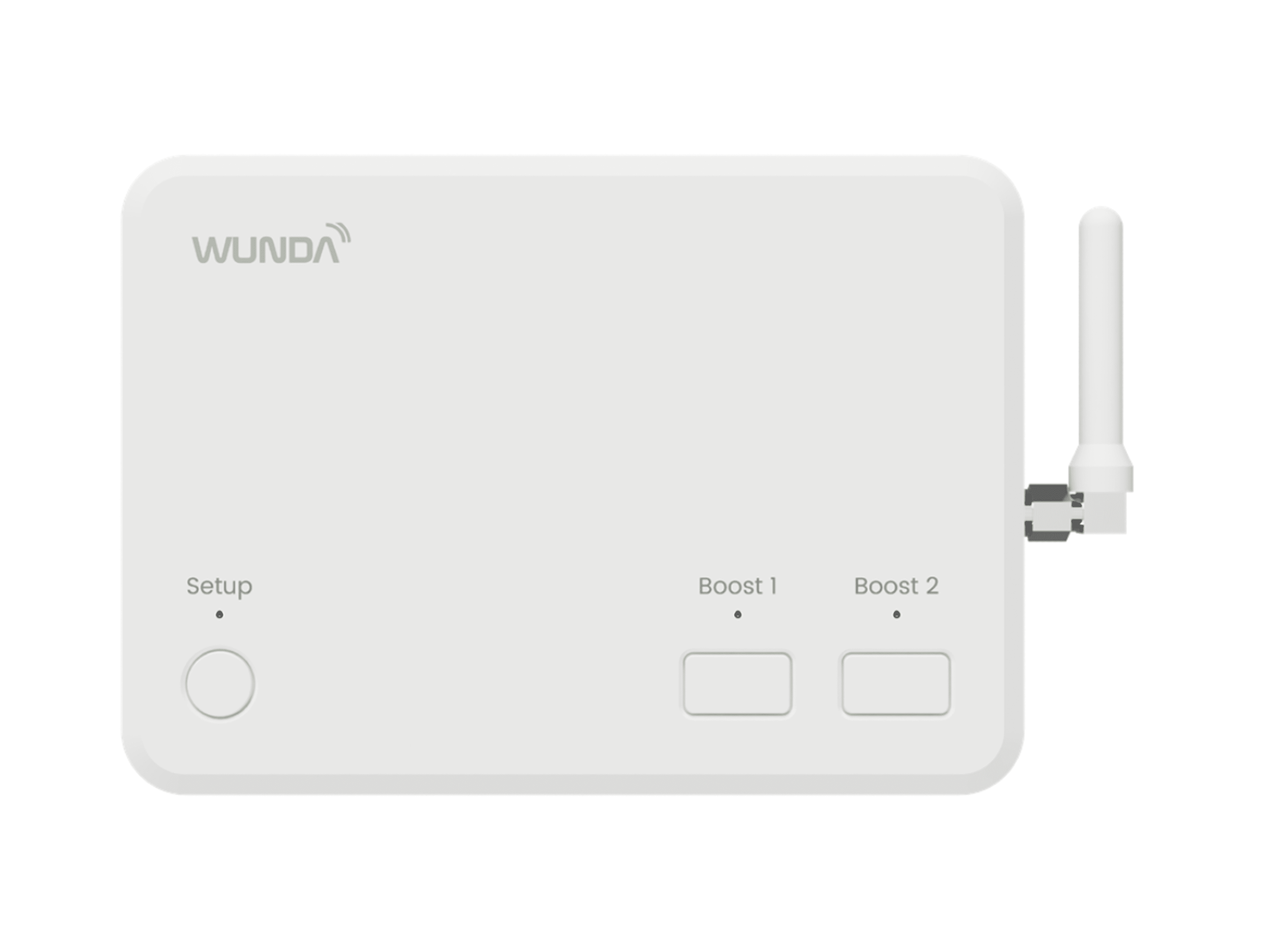
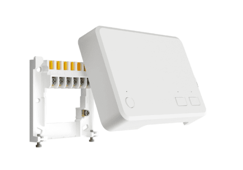
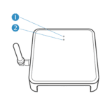
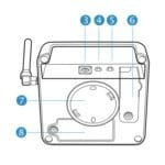
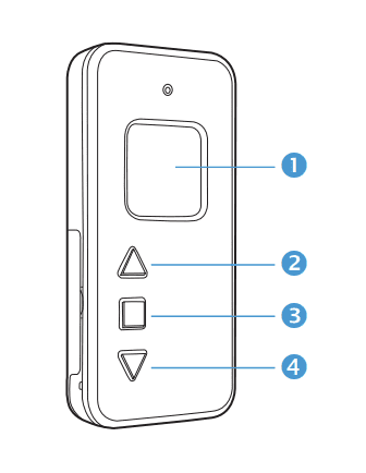
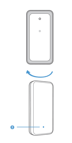
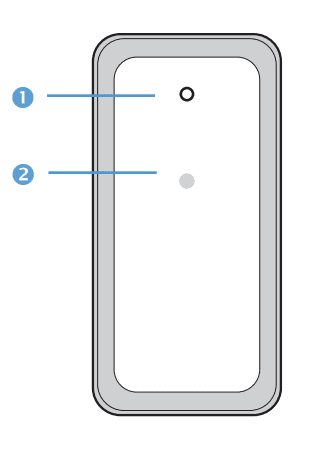
Device Appearance
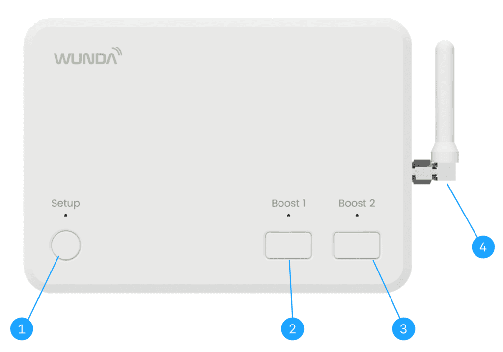
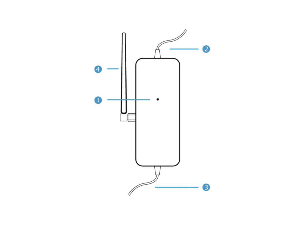
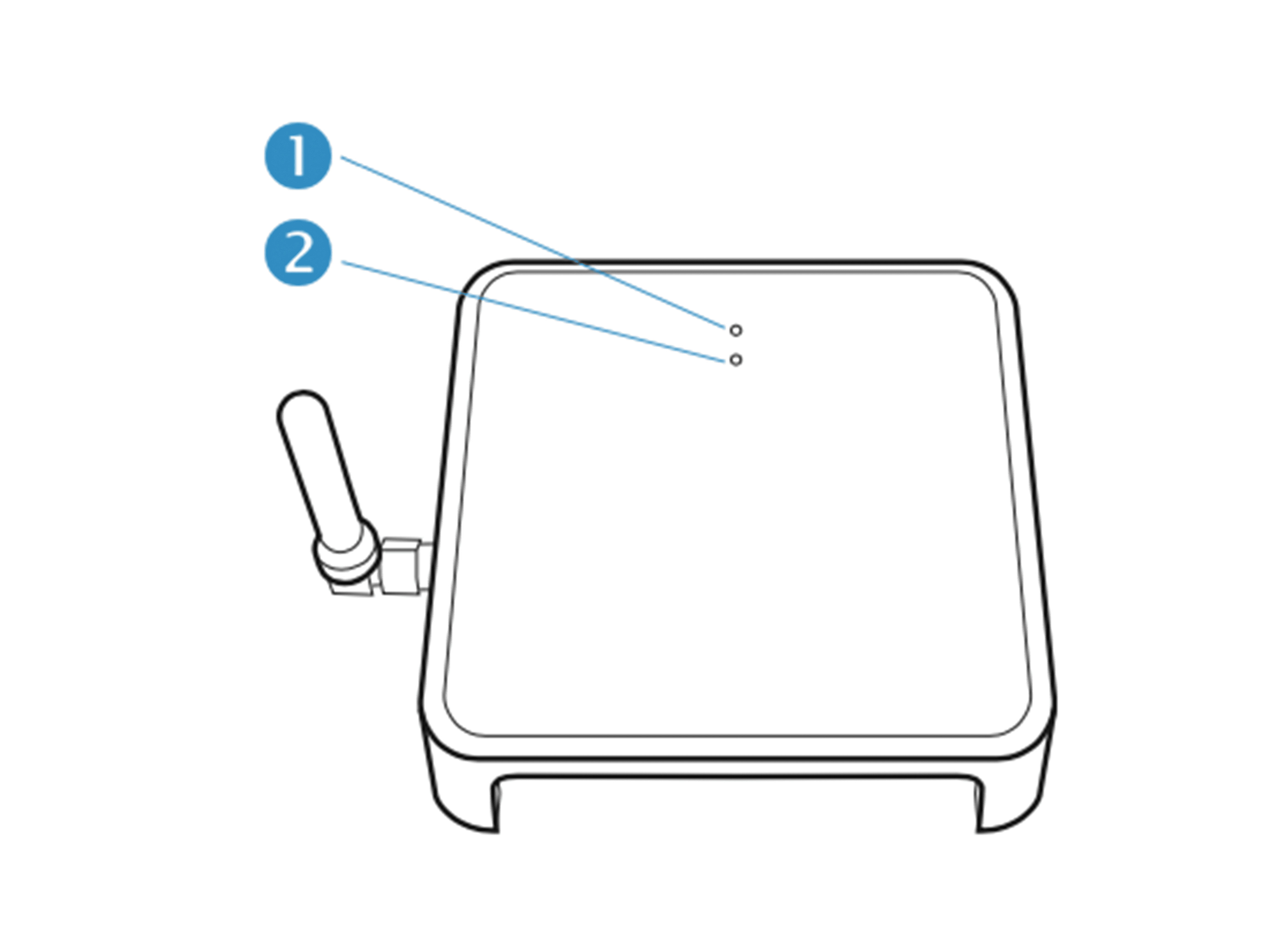
- (1) HubSwitch Power Button
- (2) First Configurable “boost” Button
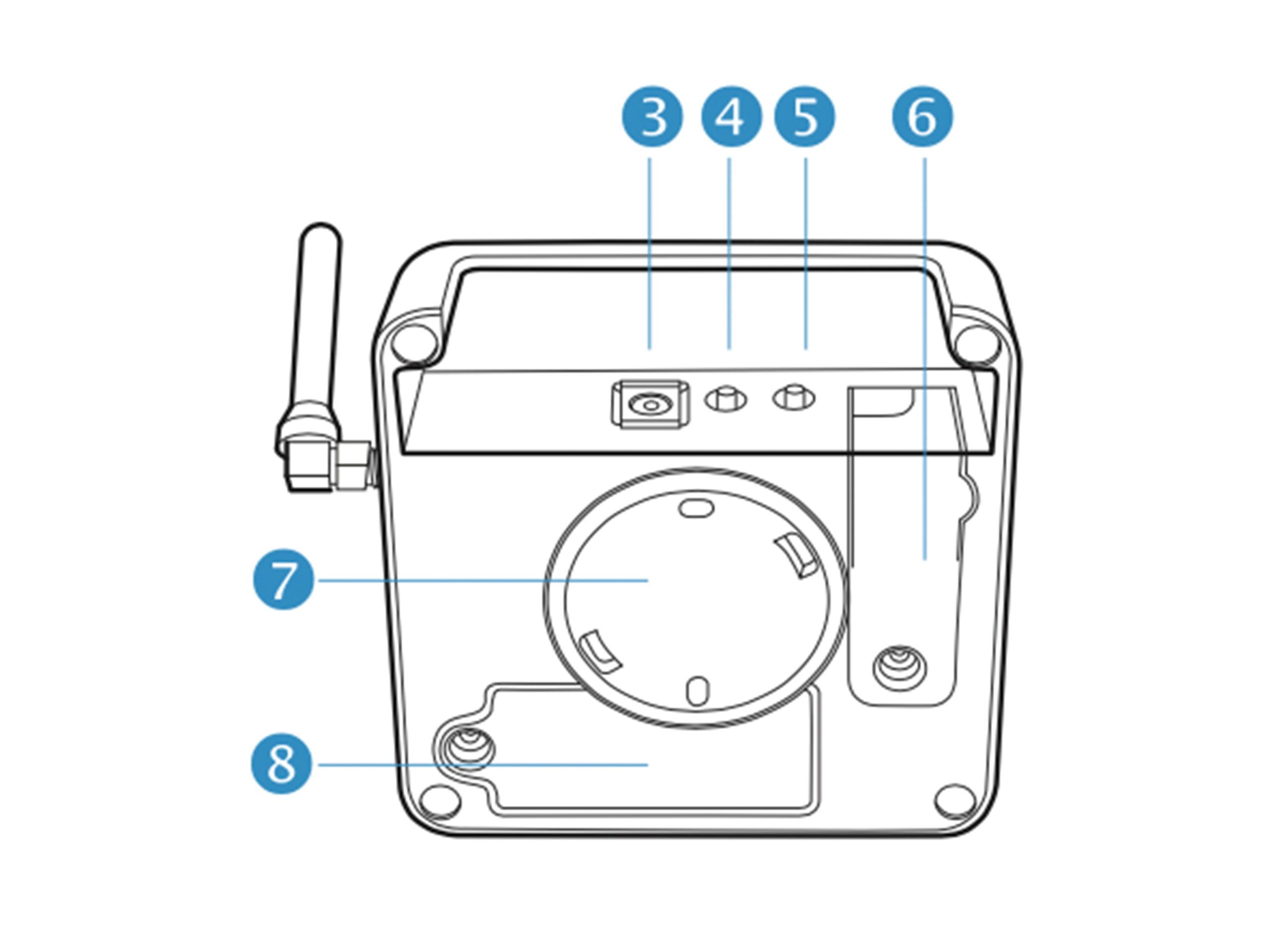
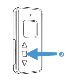
- (3) Second Configurable “boost” button
- (4) Aerial
2. Always disconnect the power supply when connecting or disconnecting the devices powered from the main device.
3. Do not use a surface mounting box as the wallplate is not designed for this purpose.
4. The installation that HubSwitch is connected to should be protect- ed with the fuses adjusted to the current loads according to applicable regulations and standards.
5. The power supply (line L & N) connected to the HUB switch must be protected by miniature circuit breakers (MCB) 3A, Characteristic B
6. Before the installation, read the terms and conditions of the warranty and these instructions. Improper installation or use against these instructions will void the warranty.
7. All repairs to the device should be carried out by the technical service. Otherwise, it will void the warranty.
8. This device should not be operated by minors, people with reduced physical or mental abilities or with lack of experience or knowledge of the equipment, except if supervision and instruction for the safe use of the equipment is provided in such a manner that all the associated hazards are understood.
9. If a non-detachable power cord is damaged, it should be replaced by the manufacturer or a technical service worker, or a qualified person in order to avoid a hazard.
10. Do not install the device with mechanically damaged casing or damaged/broken cables.
11. The device must not be exposed to water or excessive humidity resulting in steam condensation (e.g. caused by rapid changes of the ambient temperature).
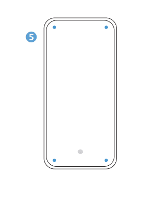
Mounting to the Wall-plate
Option 1
The ideal location should have reasonable lighting, good access, no condensation, no extremes of temperature and a supporting surface that fully covers the back of the unit. A position with 70mm clearance to the right, 25mm above and sufficient room to access the securing screws underneath. Fix, with terminals at the top, either direct to a flat wall using wall plugs and No. 6 x 1” (25mm) woodscrews, or on a flush mounting single conduit box type UA1 (BS4662) using M3.5 x 14 bolts. Now fit the Smart HubSwitch onto the wallplate and tighten the securing screws. Check the 3A fuse, and switch on the mains.
Option 2
Loosen the securing screws on the old controller/programmer and unplug it. Check that there is 70mm clearance to the right of the wallplate and 25mm above it. Check the wiring diagram for your product model to compare terminals and, if necessary, change the wiring of the wall- plate to suit. Now fit the Smart HubSwitch onto the wallplate and tighten the securing screws. Check the 3A fuse, and switch on the mains.
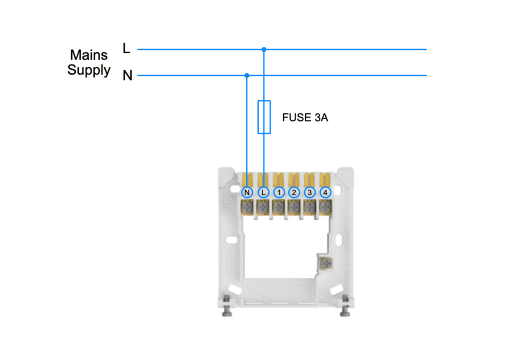
Power supply and fuse protection
An appropriate disconnect device shall be provided as part of the building installation.
The power supply (line L & N) connected to the HUB switch must be protected by miniature circuit breakers (MCB) 3A, Characteristic B
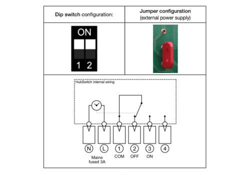
Wiring Diagrams
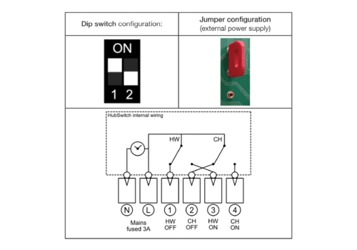
Option 1a
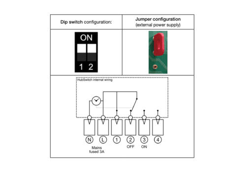
Option 1b
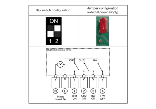
Option 2
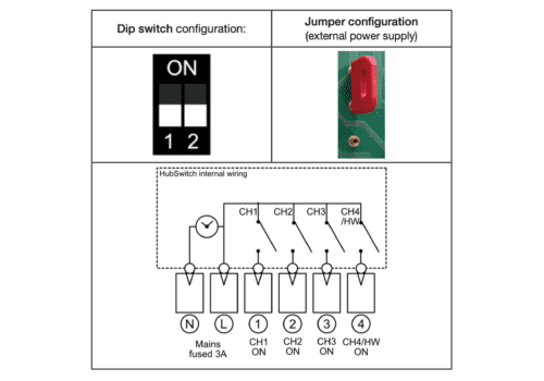
Option 3
Option 4
Boilers with OpenTherm
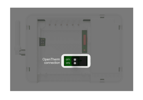
Existing OpenTherm Installation
- Remove the OpenTherm cables from the existing controller or thermostat.
- Wire the Open Therm cables to the Open Therm connector provided with Smart HubSwitch. It does not matter which way the cables are wired.
- Insert the OpenTherm Connector into the Open Therm Socket on the backside of the hubSwitch
- Wire L & N on the wallplate from a seperate supply with a 3a fuse.
- Mount the HubSwitch onto the WallPlate
Testing the system
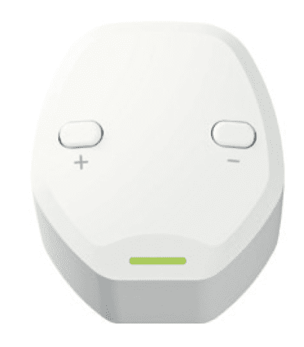
Boost 1 & Boost 2 Buttons
Boost 1 and Boost 2 buttons are fully configured via dedicated Smart HubSwitch Application (available for Android and iOS).
You can configure them in your App System Settings to boost heating and/or hot water. Pressing once either of those buttons will trigger configured functionalities and signalled by a solid green LED situated just over buttons. Each button has its own corresponding LED.
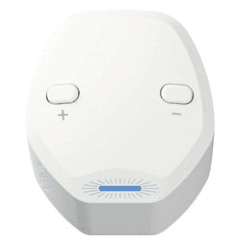
Setup/Power button
After installation of the Smart HubSwitch onto wallplate, all configura- tion of the Smart HubSwitch is done via application. You have to press Setup button once (LED situated over Setup button will flash white) and follow the steps shown within the application.
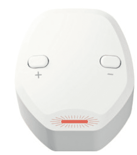
Setup LED
- flashes Blue – No WiFi Connection
- flashes Green – Connected to WiFi
- solid Green – Connected to WiFi and Server
- flashes white – Configuration mode – no connection to mobile device (with application installed)
- solid white – Configuration mode – connected to mobile device (with application installed)
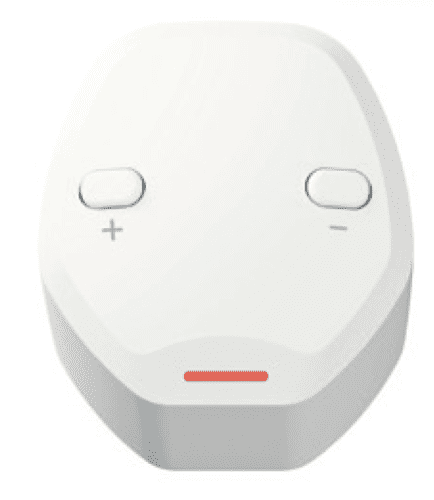
BOOST 1 LED
- LED is off – BOOST 1 is inactive
- solid Green – BOOST 1 is active
BOOST 2 LED
- LED is off – BOOST 2 is inactive
- solid Green – BOOST 2 is active
For all of this information in PDF form, click here to download!
WundaSmart Hub v1.4

WundaSmart Hub v1.4
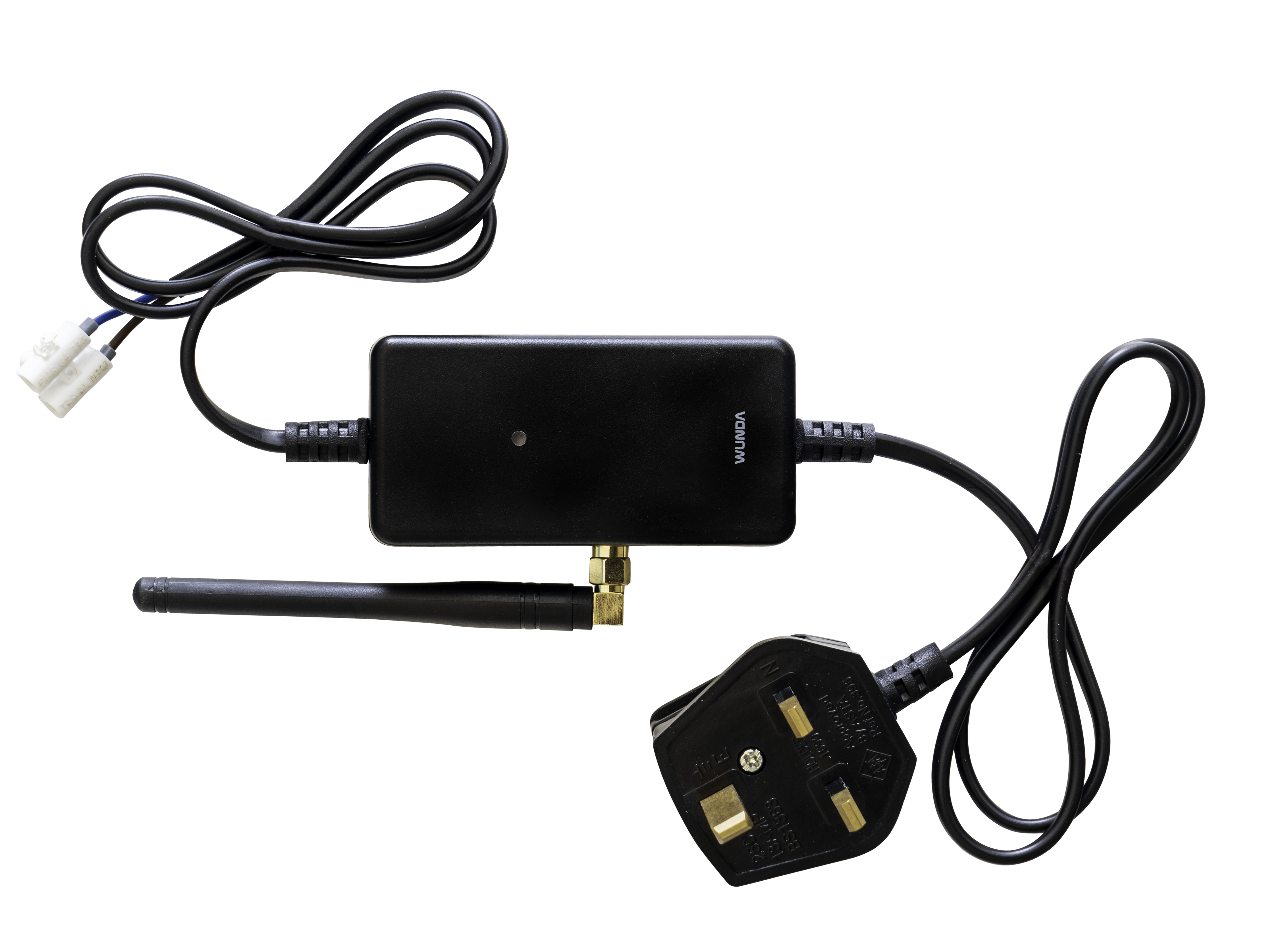
What’s in the box?
Before you start make sure your box has the following items in it.
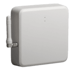
- A Hub
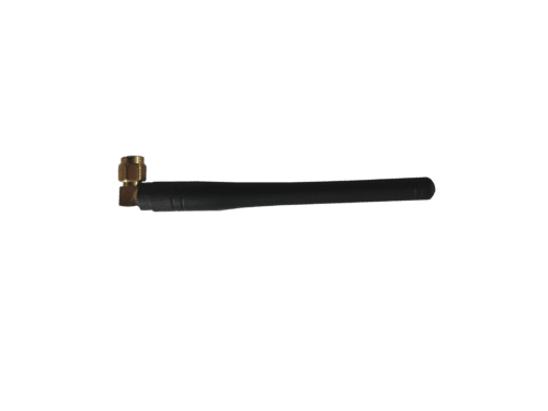
- An Aerial
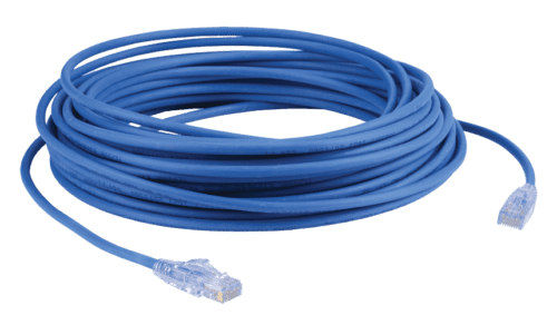
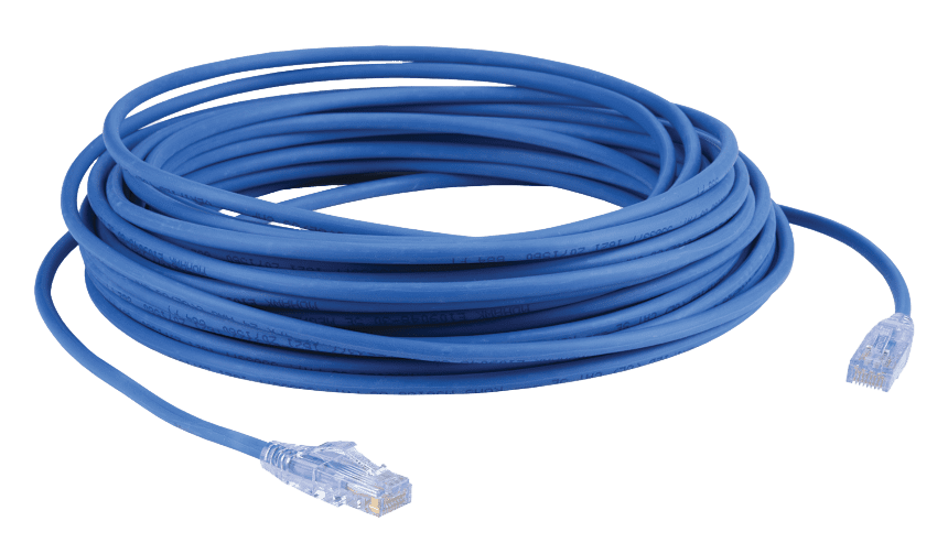
- An ethernet cable
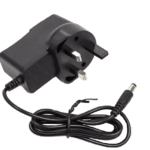
- Power Supply Unit
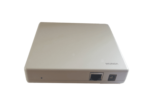
Device Appearance
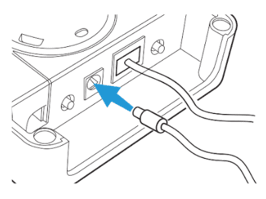
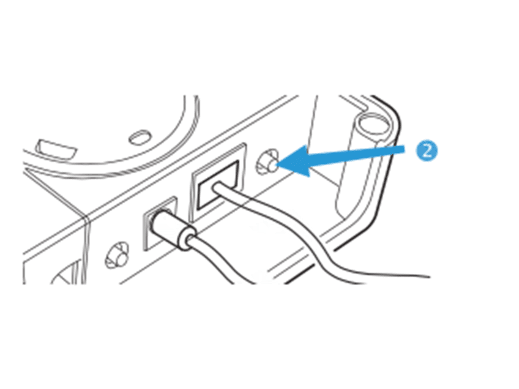
Connect SmartHub to the power supply and then to the internet router
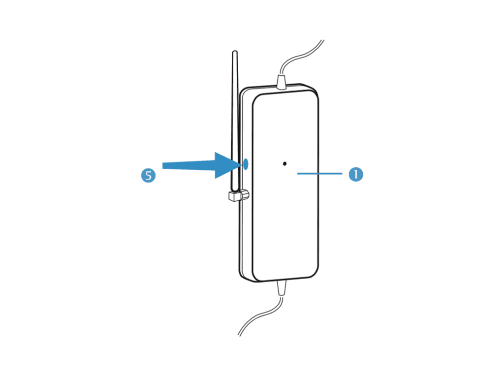
Once correctly connected the Smart Hub LED (5) will flash green. If it does
not flash green, ensure the power is switched on at the mains, and all cables are connected securely to both the Smart Hub and your internet Router.
Registering the Device
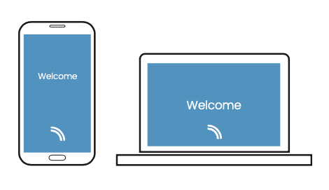
Download the WundaSmart app from the App Store or the Google Play Store. Open the WundaSmart app on your smartphone or web portal on your desktop at my.wundasmart.com and Sign in or Create an Account.
After Sign in register the device online, using either:
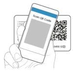
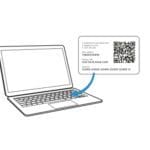
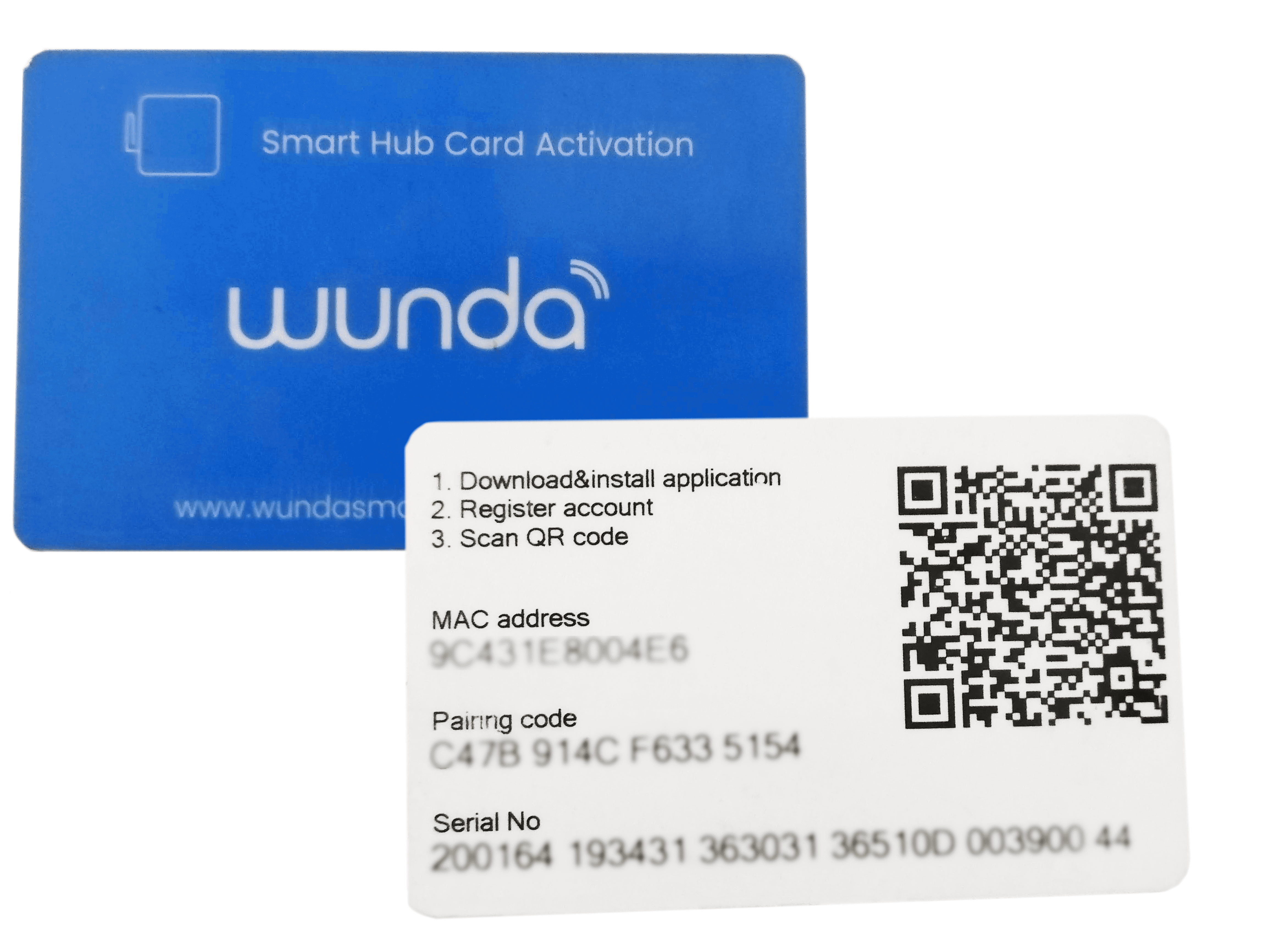
- Scan the Smart Hub’s QR code placed on Smart Hub Card Activation with your smartphone.
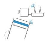
- Discover devices online in the local network with the application on your smartphone.
- Copy the Serial number and the Pairing code supplied with the device into the appropriate field on the web portal: my.wundasmart.com.
If all connections have been made correctly and you have registered your device online, your control panel will appear on the device list. Now you can start configuring the system.
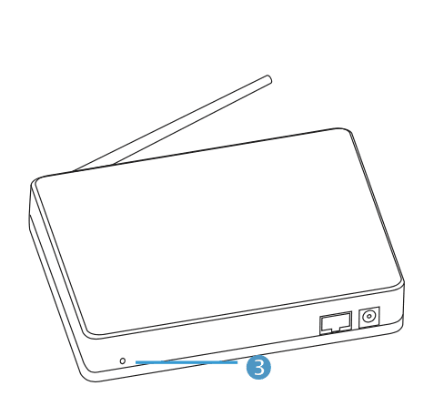
Resetting the device
- A short press button of (3) restarts the device
- To reset Login and password: Hold the button (3) for 5 seconds until the red LED comes on and will change the login and password to the default settings (login: root / password: root)
- To reset the Smart Hub to Factory settings: Disconnect the power supply from the Smart Hub, press and hold button (3) and reconnect the power when holding the button (3) until the red LED comes on and your device is reset to the factory settings.
If you want all this information as a downloadable PDF, click here.
WundaSmart Hub v2.0
WundaSmart Hub v2.0
What’s in the box
Make sure your WundaSmart Hub has come with the following:
- A smart Hub
- Ethernet Cable
- Power Supply Unit
- WundaSmart Activation Card
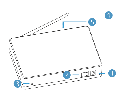
Device Appearance
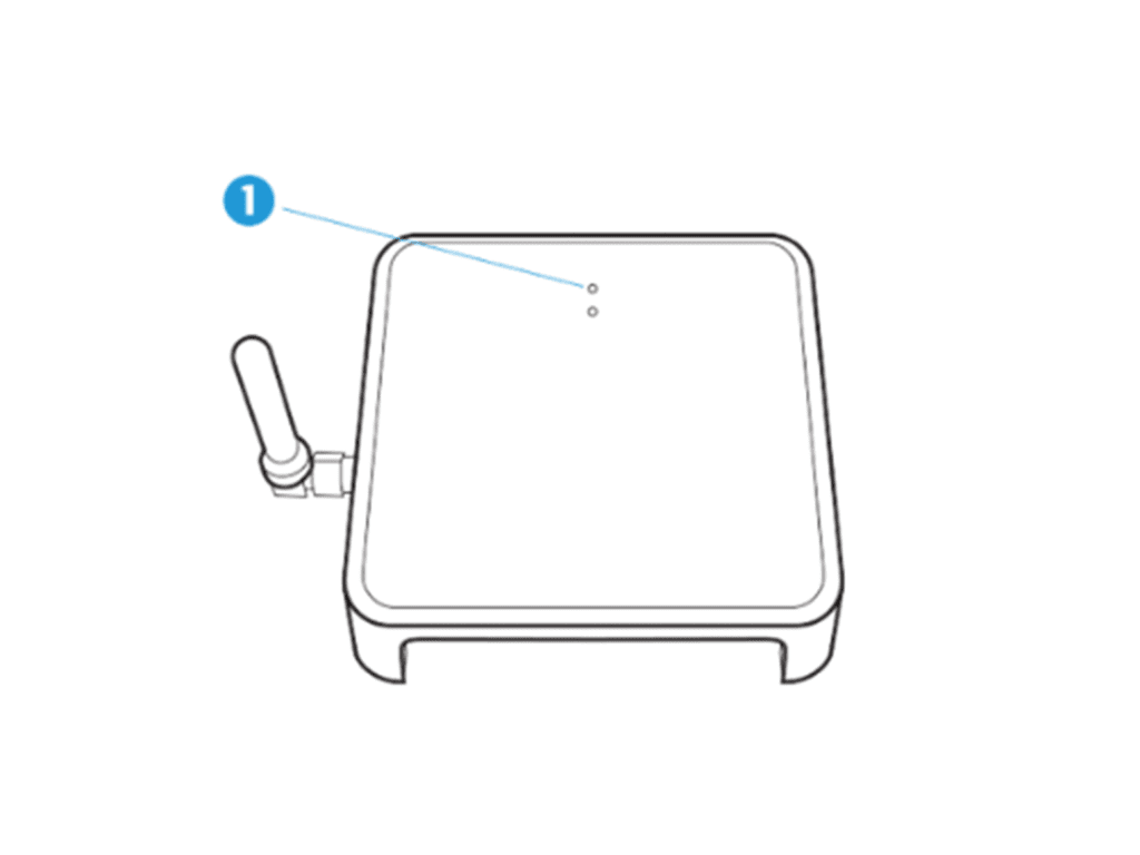
The first LED lights (1) in three colours.
-
-
- Blue to signify the hub has powered up
- Green to signify the hub is connected to the internet
- Red to signify a complete factory reset
-
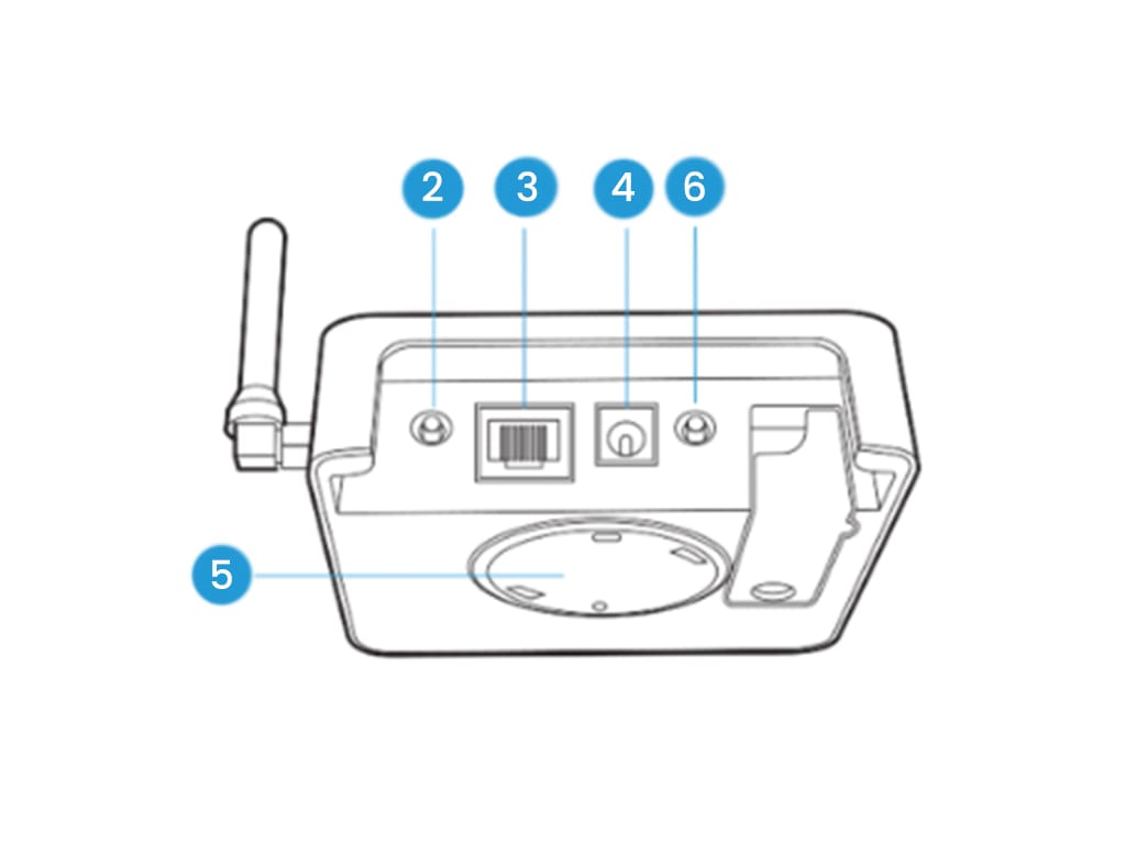
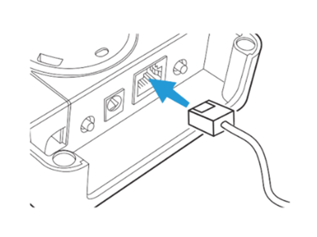
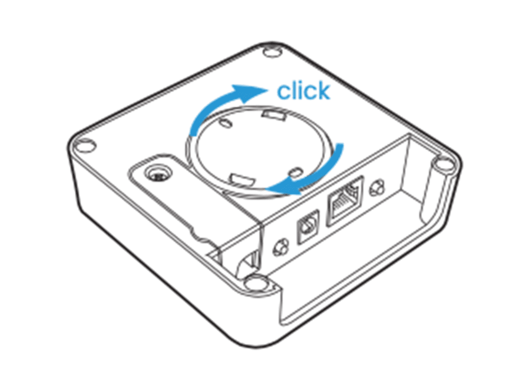
Located on the hub’s underside: (2) set up button, (3) Ethernet/LAN Connection port (4) Power supply connector, (5) wall bracket. (6) Non-functioning Relay Switch
Connect the LAN/Ethernet Cable to the router (3)
Connect the Smart Hub to the power supply (4)
Once correctly connected the Smart Hub LED (1) will flash green. If it does not flash green, ensure the power is switched on at the mains, and all cables are connected securely to both the Smart Hub and your internet Router.
Fixing to the wall (Optional)
Fixing to the wall
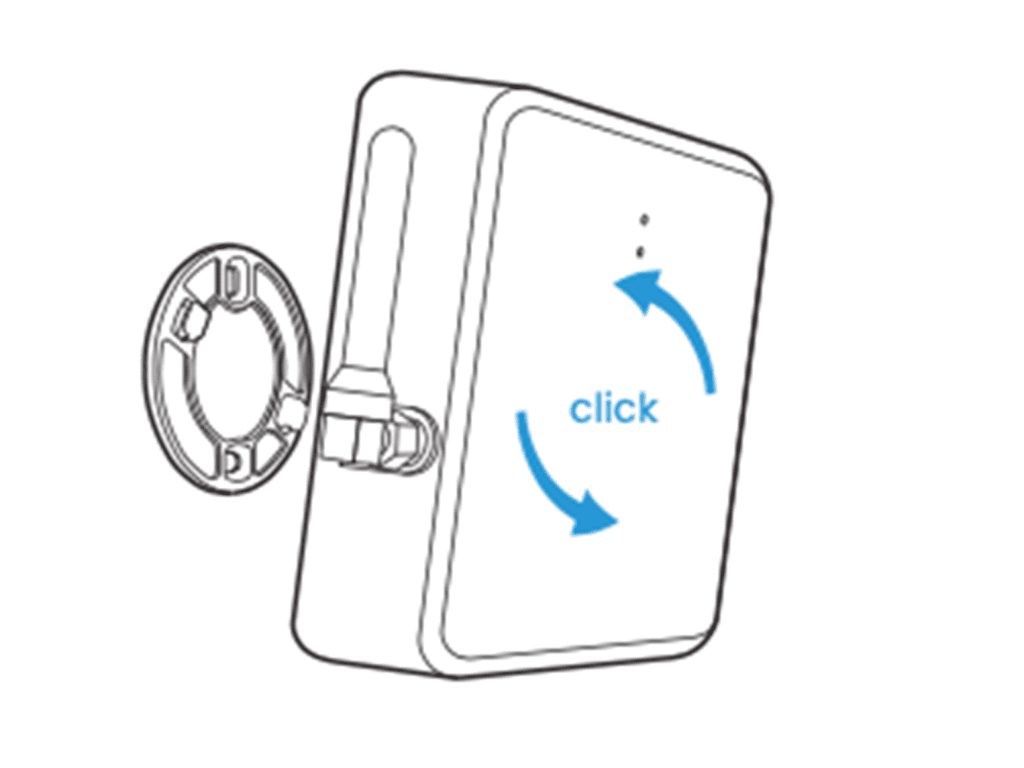
Disconnect the bracket (5) from the device.
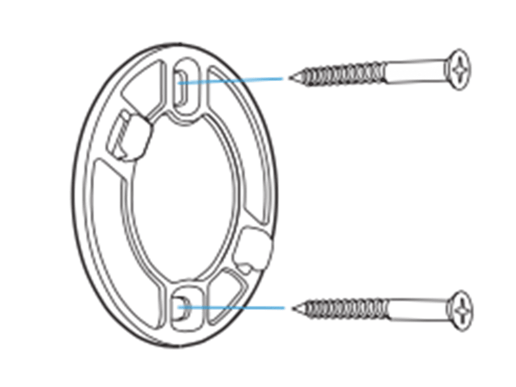
Using two screws, fix the bracket (5) to the wall,
Reconnect the Smart Hub to the mounted wall bracket
Registering the Device
Download the WundaSmart app from the App Store or the Google Play Store. Open the WundaSmart app on your smartphone or web portal on your desktop at my.wundasmart.com and Sign in or Create an Account.
After Sign in register the device online, using either:
- Scan the Smart Hub’s QR code placed on Smart Hub Card Activation with your smartphone.
- Discover devices online in the local network with the application on your smartphone.
- Copy the Serial number and the Pairing code supplied with the device into the appropriate field on the web portal: my.wundasmart.com.
If all connections have been made correctly and you have registered your device online, your control panel will appear on the device list. Now you can start configuring the system.
Resetting the device
- A short press button of (2) restarts the device
- To reset Login and password: Hold the button (2) for 5 seconds until the red LED comes on and will change the login and password to the default settings (login: root / password: root)
- To reset the Smart Hub to Factory settings: Disconnect the power supply from the Smart Hub, press and hold button (2) and reconnect the power when holding the button (2) until the red LED comes on and your device is reset to the factory settings.
If you want all this information as a downloadable PDF, click here.
WundaSmart Smart Switch v1.0
WundaSmart Smart Switch v1.0
Ensure that your Smart Hub is correctly installed and registered. (See: Smart Hub Installation Guide) and you have access to a smartphone with the WundaSmart App or a PC/Mac with Internet access
What’s in the box?
- A WundaSmart Smart Switch
Device Appearance
- LED (1)
- SPST Volt Free Switch (2)
(Brown – COM) (Blue – NO) - Power Source (3)
- Aerial (4)
- Recessed Reset Button (5)
Device set up and Installation
CAUTION: We recommend installation is carried out by a competent professional. Ensure power is isolated and standard safe working practice is followed.
- Remove product from it’s packaging. Connect Aerial (4)to main body.
- Attach wires (2) to corresponding connections on device (Boiler, Heat Pump, Hot Water Tank, etc) you wish to switch.
NB – Please refer to Manufacturers instructions to confirm if your device requires low voltage or high voltage switching. - Connect the Smart Switch to the power supply (3)
Device Pairing
- Open the WundaSmart application and log in to your Smart Hub
- Select the Devices from main menu and choose Add new device
- Select Smart Switch for gas boiler or Smart Switch for hot water tank
- You have 30 seconds to pair the Smart Switch
- Press the button(5)located on the Smart Switch side and wait until the LED(1)starts emitting continuous green light. (about 8 seconds)
- The installed Smart Switch will appear on the device list.
- The LED(1)indicates the pairing with the HUB using two colours status’:
- Green light to signify the switch is paired with SmartHub
- Red to signify the switch is not connected to the SmartHub.
- Once paired, the LED(1)indicates relay status: During normal operation flashes every 10 seconds:
- Green, if the relay is on (closed contacts: COM-NO, open contacts: COM-NC)
- Red, if the relay is off (closed contacts: COM-NC, open contacts: COM-NO)
If you want all this information as a downloadable PDF, click here.
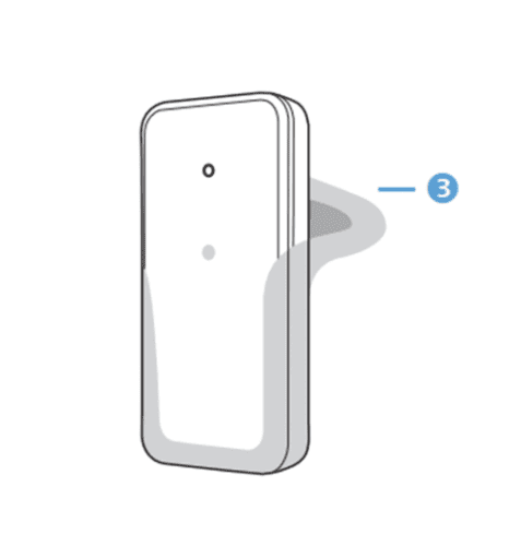
WundaSmart Smart Switch v2.0
WundaSmart Smart Switch v2.0
Ensure that your Smart Hub is correctly installed and registered. (See: Smart Hub Installation Guide) and you have access to a smartphone with the WundaSmart App or a PC/Mac with Internet access
What’s in the box?
- A WundaSmart Smart Switch
- Power Supply Unit
- Three Wire Cable (2.5m)

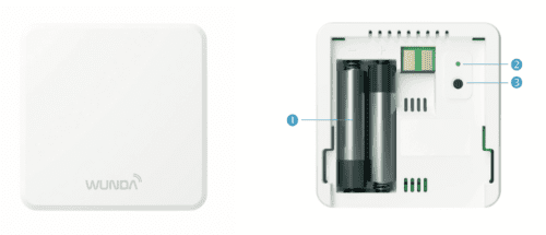
Device Appearance
The first LED (1)indicates the pairing with the HUB and light in two colours:
- Green light to signify the switch is paired with HUB.
- Red to signify the switch is not connected with the HUB
The second LED (2) inidicates relay status:
During normal operation flashes every 10 seconds:
- Green if the relay is on (closed contacts: COM-NO, open contacts: COM-NC)
- Power Source (3)
- Aerial (4)
- Recessed Reset Button (5)
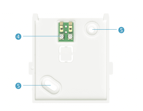
Turn off the power for your installation. Connect the three-wire cable to the Smart Switch terminal in block (6) as shown in main drawing below:
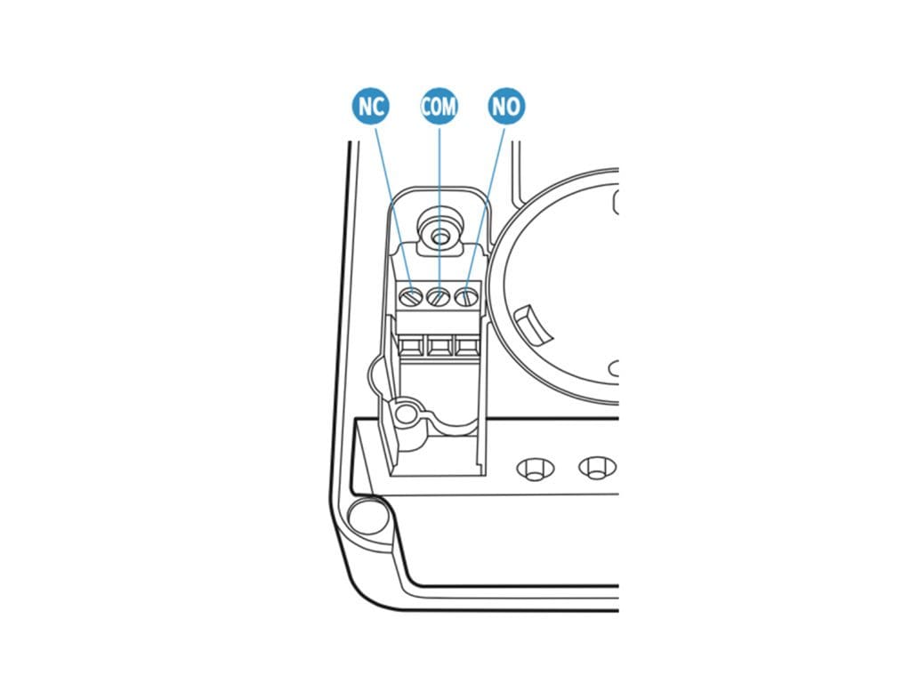
Attach wires to corresponding connections:
- black wire connect to NO – normally open
- brown wire connect to COM – common
- grey wire connect to NC – normally close (optional)
Close terminal compartment with cover and turn on the power in your installation.
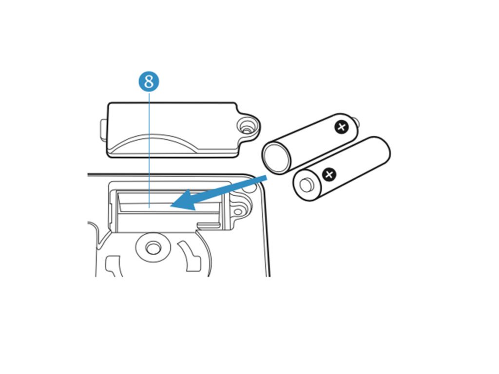
Connect the Smart Switch to the power supply (3) or put two AAA 1.5V batteries in to the compartment (8)
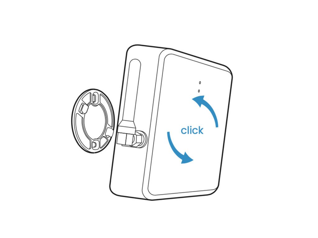
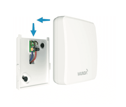
Fixing to the wall (Optional)
Disconnect the bracket (7) from the device
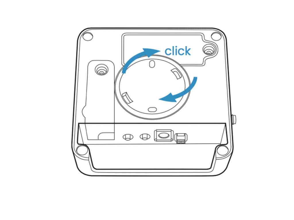
Using two screws fix the bracket (7) to the wall
 Reconnect the Smart Switch to the mounted wall bracket
Registering the device
Open the WundaSmart application and log in to your Smart Hub, select the Devices from the main menu and choose “Add new device”. Select Smart Switch for central heating or Smart Switch for hot water tank.
- You have 30 seconds to pair the Smart Switch. Press the button (4) located on the Smart Switch underside and wait until the LED (1) starts emitting continuous green light. (about 8 seconds)
The installed Smart Switch will appear on the device list.
TEST mode of the relay
At any time (even when the relay is not paired to the Wundasmart App) you can press and hold the (5) button, the LED (2) will light up with continuous light, in the following color:
- Green, if the relay is on (closed contacts: COM-NO, open contacts: COM-NC)
- Red, if the relay is off (closed contacts: COM-NC, open contacts: COM-NO)
- The next pressing of the button (5) changes the state of the relay and the color of the diode.
After 60 seconds from the last press of the button (5), the device will automatically return to the working mode.
You can exit the TEST mode at any point by pressing the (4) button.
For a full PDF copy of all this information and more, Click here to download
Smart Thermostat

Smart Thermostat
To install the Smart Thermostat first ensure that your Smart Hub is correctly installed and registered. (See: Smart Hub Installation Guide)
What’s in the box
• Smart Thermostat
• 2 x AAA 1.5V batteries
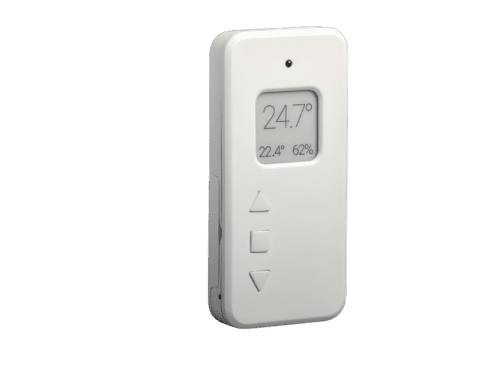
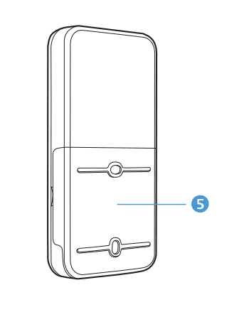
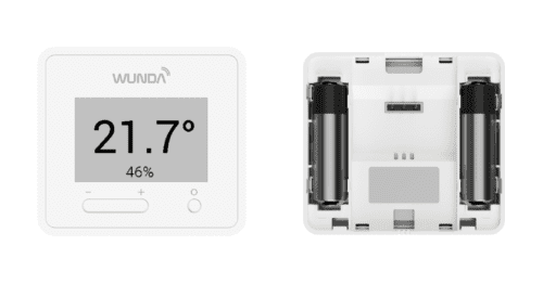
Device Appearance
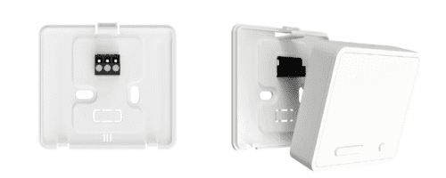
Located on the device’s back is: (5) the removable battery cover and wall bracket.
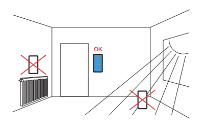
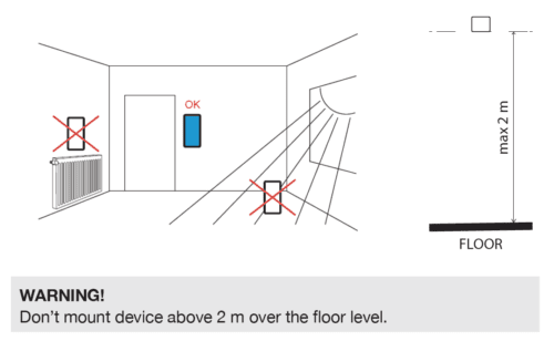
Smart Thermostat location
⚠ For the best connection between the Smart Thermostat and the Smart Hub, devices should be situated away from any metal obstacles, transformers, engines, fluorescent lamps, microwave devices, refrigerators, and other industrial equipment.
To ensure the best measurement results, the Smart Thermostat should be installed away from direct sunlight, draughts, and heat–emitting devices
(heaters, radiators, light bulbs).
Fixing to the wall
• Disconnect the bracket (5) from the device
• Using two screws, fix the bracket (5) to the wall
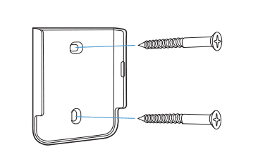
•Reconnect the Smart Thermostat to the mounted wall bracket (5)
Device pairing
• Open the WundaSmart application and log in to your device, select a Room that you wish to install the Smart Thermostat in and then enter the Settings tab.
• At the bottom of the settings menu is “Radio Devices”, select Add a new device and then Add Smart Thermostat.
• You have 30 seconds to pair the Smart Thermostat. Press the middle button (3) until paired appears on the display. The sensor has started to operate.
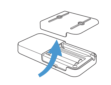
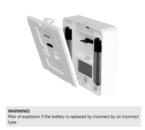
Battery replacement
Battery charge status is indicated in the application or on the Smart Thermostat display.
• Remove the battery cover (5) (wall bracket) and remove the empty batteries
• Insert new batteries as indicated on the housing.
• Reconnect the Smart Thermostat to the mounted wall bracket (5).
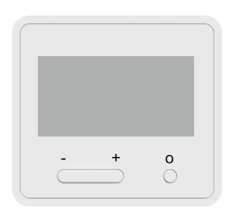
Located on the device’s face is the energy saving (1) e-ink display, and 3 control buttons:
(2) 1st button: a short press increases the setpoint temperature by 0.1 degrees, a long press by 1 degree
(3) 2nd button: a short press locks/ unlocks the weekly table, a long press activates pairing of the device
(4) 3rd button: a short press decreases the setpoint temperature by 0.1 degrees, a long press by 1 degree
If you want all this information as a downloadable PDF, click here.
Temperature Sensor

Temperature Sensor
Ensure that your Smart Hub is correctly installed and registered. (See: Smart Hub Installation Guide) A smartphone with the WundaSmart App or a PC/Mac with Internet access.
What’s in the box
• Temperature Sensor
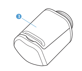
• Rubber Case
• Screwdriver
• 1 x Lithium battery
• 4 x screws
Device Installation
• Take Temperature Sensor out of the box.
• Remove cardboard inner box to find battery & 4 screws beneath
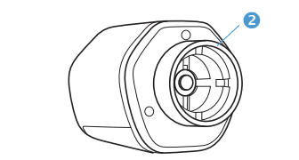
• Remove Temperature Sensor from Rubber cover (3) take care as there are no screws securing the housing
• Lay the Temperature Sensor down on a secure surface facing up and remove front cover (4) to reveal the inside Circuit Board facing up
• Place the plus side of the battery facing up towards the labelled, plus side of the battery cover
• Replace the front of the Temperature Sensor
• Turn Temperature Sensor around, place 4 screws in each corner, secure with screwdriver (5)
Device pairing
• Press and hold the small button on the back for 30 seconds to pair with Hub / App
• Open the WundaSmart application and log in to your device, select a Room in which you wish to install the Temperature sensor, and then enter the Settings tab
• At the bottom of the settings menu is “Radio Devices”, select Add a new device and then Add Temperature Sensor
• You have 30 seconds to pair the Temperature Sensor
Temperature Sensor location
To ensure the best measurement results, the Smart Temperature Sensor should be installed away from direct sunlight, draughts, and heat–emitting devices (heaters, radiators, light bulbs).
(1) Paring LED
(2) Temperature sensor
(3) Pairing button
If you want all this information as a downloadable PDF, click here.
Screenless Thermostat v2

What’s in the box?
- Screenless Thermostat v2
- 2 × AAA Alkaline Battery
(1) 2 × AAA Alkaline Battery
(2) Pairing LED
(3) Pairing Button
(4) Terminal for attaching optional floor probe
(5) Wall mounting holes for 2 × screws (5×30 mm or 4×20mm)
To install your Screenless Thermostat v2
- Put the batteries into the compartment
- For the best results, we recommend mounting the screenless thermostat to the wall out of direct sunlight
To Pair & Operate your Screenless Thermostat v2
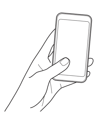
- Launch your App and choose the Room where you want to add your Smart Screenless Thermostat.
- Press Add Screenless Smart Thermostat button in your app, then press (3) to pair.
For a full PDF copy of all this information and more, Click here to download
Smart Square Thermostat

Smart Square Thermostat
To install the Smart Thermostat first ensure that your Smart Hub is correctly installed and registered. (See: Smart Hub instructions for installation & registration process.)
Tools required
• A smartphone with the WundaSmart App
• Philips screwdriver
• 2 x M2 screws or adhesive tape
Location
For the best connection between the Smart Thermostat and the Smart Hub, devices should be situated away from any metal obstacles, transformers, engines, fluorescent lamps, microwave devices, refrigerators and other industrial equipment. To ensure the best measurement results, the Smart Thermostat should be installed away from direct sunlight, draughts and heat–emitting devices (heaters, radiators, light bulbs).
Battery replacement
Use 2 x1.5V – alkaline battery LR6 (AA)
Remove the battery cover and insert two AA batteries. Make sure the batteries are correctly oriented.
Fixing to wall
- Disconnect the bracket from the device
- Using two screws, fix the bracket to the wall
- Reconnect the Smart Thermostat to the mounted wall bracket.
Device pairing
- Open the WundaSmart application and log in to your device, select a Room that you wish to install the Smart Thermostat in and then enter the Settings tab.
- At the bottom of the settings menu is “Radio Devices”, select Add a new device and then Add Smart Thermostat.
- You have 30 seconds to pair the Smart Thermostat. Press the O button until paired appears on the display. The sensor has started to operate.
Located on the device’s face is the energy saving e-ink display and 3 control buttons:
– button: a short press decreases the setpoint temperature by 0.1 degrees, a long press by 1 degree
+ button: a short press increases the setpoint temperature by 0.1 degrees, along press by 1 degree
o button: a short press locks/unlocks the weekly table, a long press activates pairing of the device
Press and hold – button and o button for 2 seconds to change between manual and program settings.
Tap the o button to show the current set temperature.
Located on the device’s back is: the removable battery cover and wall bracket.
Safety instructions
Cleaning
- Use only a dry, soft cloth for cleaning.
- The use of water or organic solvents is prohibited.
Battery change
- It is forbidden to recharge an exhausted battery!
- Replace the battery with an identical, fully charged model.
- The battery replacement process is described in the section “Installing the battery”.
Battery disposal
- Radio-controlled system components are powered by LR6 (AA) type batteries.
- When replacing batteries, be sure to dispose of used components properly.
- In accordance with the law in force in a given territory, batteries
For a full download of all this information in a PDF. Click here
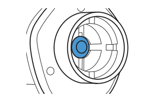
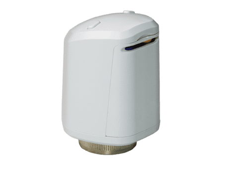
Smart Radiator Heads With Buttons

Smart Radiator Heads With Buttons
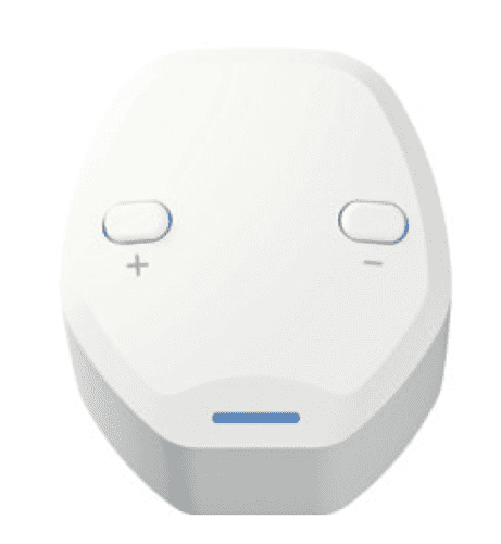
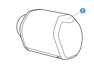
Welcome to your Smart Radiator Head
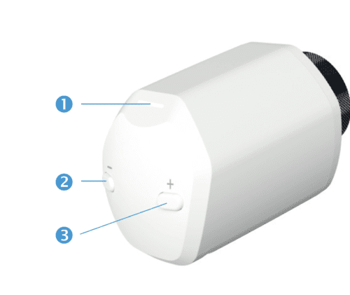
(1) Control LED,
(2) Decrease temperature –
(3) Increase temperature +
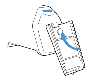
(4) Battery compartment
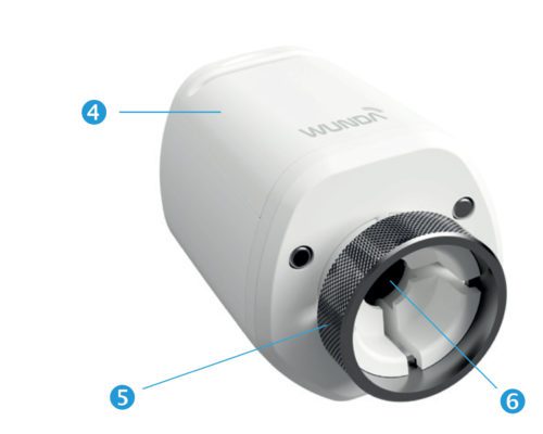
(5) Mounting ring
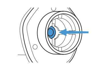
(6) Motorised pin
To install the Smart Radiator Head first ensure that your Smart HubSwitch is correctly installed and registered. (See: Smart HubSwitch Installation Guide).
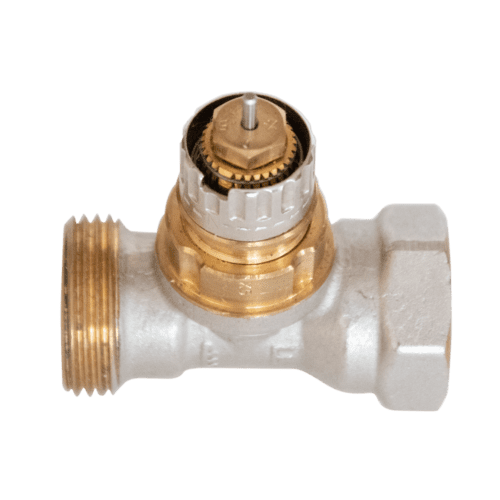
Mounting Smart Radiator Head on valve
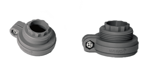
The Smart Radiator Head has a mounting ring designed for M30×1.5 threaded TRVs. For radiators with any other valve type, an adapter should be used.
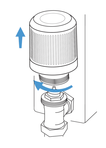
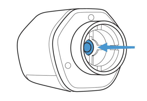
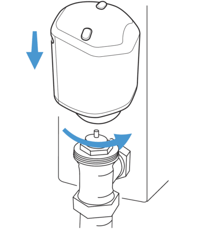
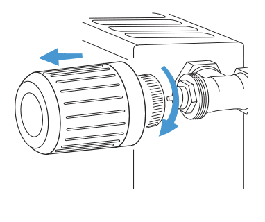
A. Detach the used radiator head from the radiator and place proper adapter if required.
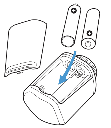
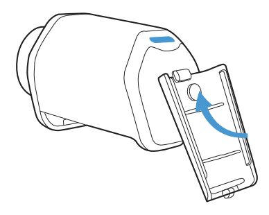
B. On your Smart Radiator Head, put the batteries into the compartment (4) or remove the Tabs.
C. Press buttons (2)(3) on the front for 5 seconds until the LED (1) emits continuous white light and starts to buzz indicating the valve pin pusher (6) inside the Radiator Head will retract as far as possible.
D. You now have 60 seconds to install the Smart Radiator Head onto the valve with the motorised pin retracted.
E. After 60 seconds the motorised pin will return to the starting position. When installed, the Smart Radiator Head will carry out automatic calibration.
PLzuRoygelNFZ6dttnp37FXetxLSgL5Yz2&index=8
Smart Radiator Head connection

A. Open the WundaSmart application and log in to your system, select the Room in which you wish to install the Smart Radiator Head in and then enter the Setting tab.
B. Select Radio Devices at the bottom of the settings menu, choose ‘add a new device’ and then select ‘Add Head’.
C. You have 30 seconds to pair the head. Again press buttons (2)(3) on the front of the Smart Radiator Head and wait until the LED (1) starts emitting continuous green light. (about 8 seconds)
D. The installed Smart Radiator Head will appear on the device list in the Room.
Operating Smart Radiator Head
By pressing buttons (2) or (3) You can switch between the preset temperatures in your app. Manual changes are valid for 2 hours.
 .
.  .
. 
Blue LED: Reduced Temperature Green LED: Comfort Temperature Red LED: Comfort + Temperature
Blinking Blue LED: Raditor Head is Closed (Antifreeze Settings)
Blinking Red LED: Raditor Head is Open (max 35°C)
Safety instruction
Cleaning
Use only a dry, soft cloth for cleaning. The use of water or organic solvents is prohibited.
Battery change
It is forbidden to recharge exhausted non rechargeable batteries! Use 2×1.5V – alkaline battery LR6 (AA). Remove the battery cover and insert two AA batteries. Make sure the batteries are correctly oriented. The battery replacement process is described in the section “Smart Radiator Head Fitting”.
Battery disposal
Radio-controlled system components are powered by LR6 (AA) type batteries. When replacing batteries, be sure to dispose of used components properly.
Smart Radiator Heads

To install the Smart Radiator Head first ensure that your Smart Hub is correctly installed and registered. (See: Smart Hub Installation Guide) The Smart Radiator Head has a mounting ring designed for M30×1.5 threaded TRVs. For radiators with any other valve type, an adapter should be used. The
packaging contains:
- Smart Radiator Head
- 2 x AA 1.5V batteries
Tools required:
A smartphone with the WundaSmart App or a PC/Mac with Internet access
⚠To ensure the best connection between the Smart Radiator Head and the Smart Hub, the device should be situated far from transformers, engines, fluorescent lamps, microwave devices, refrigerators and other industrial equipment.
• Detach the used radiator head from the radiator and place adapter if required;
• Remove the battery cover from the Smart Radiator Head. Insert the two AA batteries as indicated;
• Touch the battery cover (3) to the head front (1) for 5 seconds until the LED emits continuous white light and starts to buzz indicating the valve pin pusher is retracting.
• Remove the battery cover (3) from the top of the Smart Radiator Head. The pin inside the head will retract as far as possible
• You now have 60 seconds to install the Smart Radiator Head on to the valve with the pin retracted.
• After 60 seconds the pin will return to the starting position. When installed, the Smart Radiator Head will carry out automatic calibration.
Smart Radiator Head connection
Open the WundaSmart application and log in to your Smart Hub, select the Room in which you wish to install the Smart Radiator Head in and then enter the Setting tab. At the bottom of the settings menu is “Radio Devices”, select “Add a new device” and then select “Add Head”
• You have 30 seconds to pair the head. Again touch the battery cover to the top of the Smart Radiator Head and wait until the LED starts emitting continuous green light. (about 8 seconds)
The installed Smart Radiator Head will appear on the device list in the Room.
• View one: (1) control LED
• View two: (2) mounting ring
• View three: (3) battery compartment
For a full PDF copy of all this information and more, Click here to download
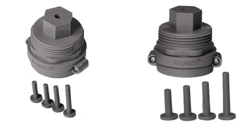
 |
34 mm with 4 Adapter notches | Danfoss RAV | Includes a cup-pin |
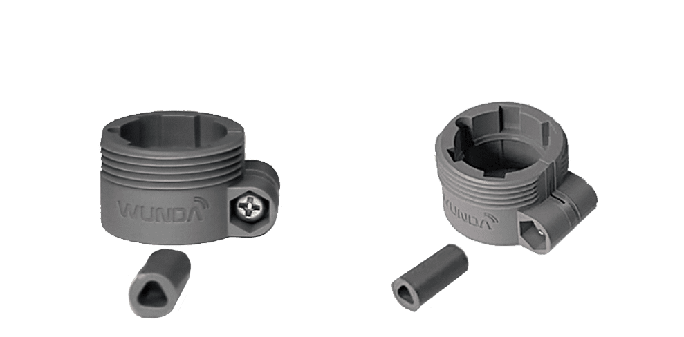 |
No thread 20mm bzw. 23mm with 4. Notches | Danfoss RA | Includes Screw |
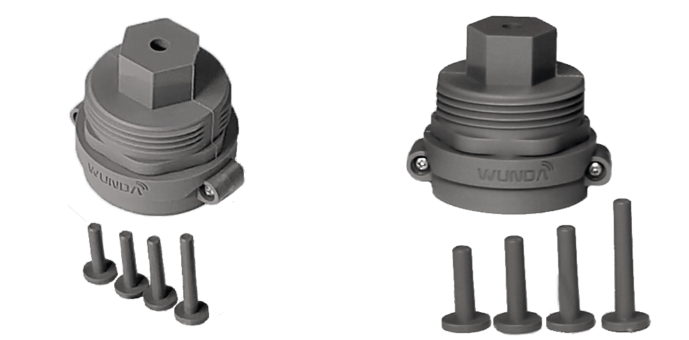 |
Thread M28 x 1.5 to M30 x 1.5 |
|
Includes 4 pins |
Radiator Head Adaptors
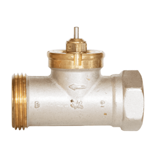
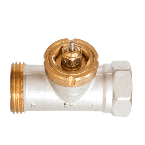
- Danfoss RAV
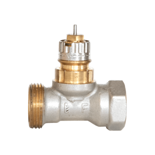
- Danfoss RA
- Comap
- Hertz,
- Markardys
- Pont a Mousson
- Remagg
- Sam bzw
- Slovarm
- TA
Smart Connection Box

Caution!
Before starting the installation process make sure that there is no voltage on the connection cables. Installation should be performed with a flat screwdriver (up to 3mm in diameter). To ensure correct operation of the device, make sure that it is transported, stored and used appropriately.
Note: large metal objects located in the vicinity of or between the Smart Hub and the Smart Connection Box may have a negative effect on the quality of radio transmission between the devices. External antenna should be placed vertically. The device should be connected to a single-phase power system according to the standards in place.
The connection method is described in this manual. Dismounting of the housing, incorrect assembly or use, and operation contrary to the guidelines set forth in this manual will result in the loss of product warranty and cause the risk of electric shock.
General information
The Smart Connection Box controls Electronic Actuators, circulating pump and heat source or zone valve. The Smart Connection Box is a part of the heat management system for your home.
One Smart Hub supports up to 4 Smart Connection Boxes.
The Smart Connection Box has a range of functions:
Control Electronic Actuators
Supports up to 12 heating zones;
Controls the circulating pump manifold;
Is equipped with a potential-free contact (relay) for controlling an external heating source/ zone valve.
Connecting to manifold
The Smart Connection Box must be installed in a suitable location above the manifold within reach of the actuator power cables.
All installation and connection steps should be performed by appropriately qualified and authorized persons in accordance with applicable regulations and standards.
- Installation of the Smart Connection Box should be installed via fused spur.
- Isolate and turn off spur from mains power and connect the Smart Connection Box to the spur (1)
- Connect to electronic actuators installed on the manifold in correct order to relevant contacts (2)
- Connect manifold pump to contact no (6)
- If you want to switch heat source/ zone valve, connect to relay output (3)
- Turn on the power for your Smart Connection Box
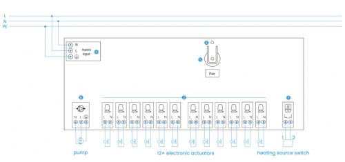
Wiring diagram:
Registering the device
Ensure that your Smart Hub is correctly installed and registered.
Open the WundaSmart application and log in to your Smart Hub, select the Devices from the main menu, and choose Smart Connection Box.
You have 30 seconds to pair the Smart Connection Box. Press and hold button (5) and wait for the LED light (4) to turn green.
The installed Smart Connection Box will appear on the device list.
Configure heating zones (rooms) in your application.
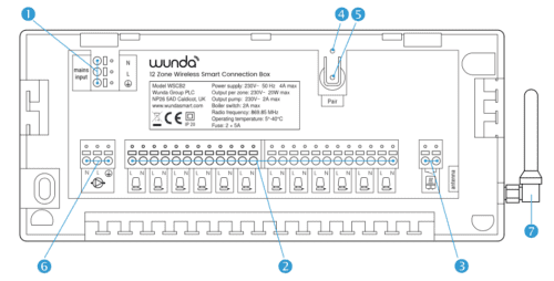
Device appearance
The device consists of the following components:
(1) 230V power mains input
(2) 12 outputs for electronic actuators
(3) Heating source switch, max 3A
(4) Status LED
(5) Pairing button
(6) Relay output for 230V the circulating pump, max 2A
(7) antenna
For a full PDF copy of all this information and more, Click here to download