Before proceeding to Phase 4, ensure that Phase 3 has been fully completed.
These instructions are strictly for use with Wunda systems only. Using them with any other system may result in serious performance issues, system failure, or invalidation of your warranty.
Phase 4 – Connecting the Heat Source and Configuring Controls
This phase covers the final stages of commissioning your underfloor heating system. At this point, the manifold should be installed, the pipework connected, and the system filled according to the previous installation phases.
The purpose of this phase is to:
- Connect the manifold to the heat source
- Remove any trapped air from the system
- Protect the system with inhibitor
- Wire and configure the heating controls
- Pair smart devices with the WundaHome app
- Balance the system and set flow rates
Correct commissioning is essential to ensure efficient operation, accurate temperature control, and reliable long-term performance.
Ensure all electrical work is carried out by a suitably qualified professional.
STEP 1 – Pre-connection pressure testing
Materials required
- Pressure testing equipment
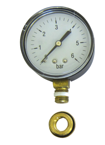
- Pressure gauge
- Manifold assembly
- Pipe layout drawing
Before connecting the manifold to the heat source, the underfloor heating system should be pressure tested.
Pressure testing confirms that all pipework, manifold connections, and fittings are watertight before heated water is introduced into the system. Identifying leaks at this stage can prevent costly remedial work later.
Carefully inspect:
- Manifold connections
- Filling and drain valves
- Pipe connections
- Isolation valves
Monitor the pressure gauge and ensure the system maintains pressure throughout the testing period.
Any pressure loss should be investigated and rectified before continuing.
Once the pressure test has been successfully completed, the manifold can be connected to the heat source.
STEP 2 – Connecting the manifold to the heat source
Materials required
- Appropriate manifold fittings
- Compression fittings
- Isolation valves
- Adjustable spanners
The manifold distributes heated water throughout the underfloor heating system. To operate correctly, each manifold requires its own dedicated flow and return connections from the heat source.
Where multiple heating systems share the same heat source, it is recommended that an S-Plan or S-Plan Plus arrangement is used. This allows each system to operate independently and provides separate demand signals to the heat source.
When connecting to the isolation valves on either side of the blending valve, use suitable 1-inch male iron compression fittings.
Recommended pipe sizes:
- 2–4 port manifolds – 15mm feeds
- 4–8 port manifolds – 22mm feeds
- 8–12 port manifolds – 28mm feeds
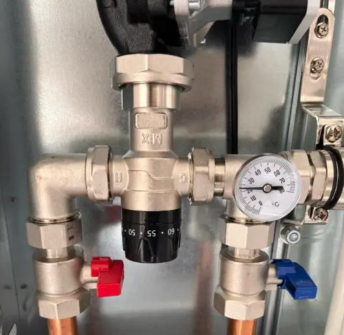
Before introducing heated water into the system, ensure the blending valve is fully closed.
This helps prevent excessive temperatures reaching the floor circuits during commissioning.
Installer tip
Double-check the flow and return connections before filling the manifold. Reversed connections can cause balancing and temperature control issues during commissioning.
STEP 3 – Venting air from the manifold
Air trapped within a heating system can reduce circulation, create noise, and prevent the correct flow rates from being achieved.
Before opening the underfloor heating loops, any air introduced during connection to the heat source should be removed from the manifold assembly.
When the manifold has been connected and the primary feeds are full:
- Keep all underfloor heating loops isolated.
- Ensure all flow meters are closed.
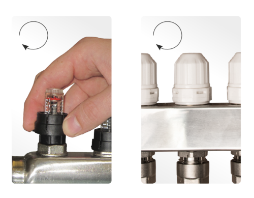
- Ensure all return valves are fully closed by rotating them clockwise.
With the loops isolated, any trapped air can be removed using the manual air vents fitted to the manifold.
This prevents air being carried into the floor circuits where it can be much more difficult to remove.
Common issue
If gurgling noises or inconsistent flow rates are experienced during commissioning, residual air may still be present within the system and further venting may be required.
STEP 4 – Adding inhibitor to the system
Materials required
- Approved heating system inhibitor
- Filling equipment
- Pipe layout drawing
Like any central heating system, an underfloor heating installation should be protected using a suitable corrosion inhibitor.
Inhibitor helps prevent:
- Corrosion
- Sludge formation
- Scale build-up
- Reduced system efficiency
The inhibitor can be introduced through any suitable filling point within the heating system.
Calculating system water volume
To determine the correct quantity of inhibitor, calculate the volume of water contained within the underfloor heating pipework.
16mm pipe:
Total loop length × 0.113 = litres
12mm pipe:
Total loop length × 0.061 = litres
Use the loop lengths shown on the supplied pipe layout drawing.
Installer tip
Always follow the inhibitor manufacturer’s dosage recommendations. Overdosing or underdosing may reduce effectiveness.
STEP 5 – Wiring and Control Setup
The following instructions relate to Wunda Smart Controls.
If using Wunda standard controls, please refer to the relevant controls fact sheet.
If using third-party controls, always follow the manufacturer’s installation and commissioning instructions.
Single-zone manifold wiring
For single-zone systems where all loops operate together, electronic actuators and connection boxes are not required.
Open all manual return valves fully by turning them anti-clockwise.
The HubSwitch can then be used to trigger:
- The brown wire of the manifold zone valve
- The live supply to the manifold pump
Ensure suitable connections are made for:
- Neutral conductors
- Earth conductors
The remaining zone valve wiring should return to the S-Plan wiring centre, with the grey and orange conductors providing the heat source demand signal.
The HubSwitch should be configured according to the equipment being controlled. Refer to the HubSwitch setup instructions for the appropriate dip switch and jumper settings.
Multi-zone manifold wiring
Multi-zone systems allow different rooms to call for heat independently.
To achieve this, electronic actuators are installed on the manifold and controlled through the Wunda connection box.
Each manifold requires its own connection box.
A maximum of four connection boxes can be connected to a single hub.
Important mounting guidance
Do not mount the connection box beneath the manifold.
This helps protect the controls from accidental water damage.
[Image showing correct connection box location]
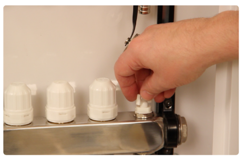
Remove the manual return valve caps and install the electronic actuators.
Retain the manual caps for future servicing, filling, or air purging procedures.
Connect each actuator to the corresponding actuator terminals within the connection box.
Outputs should be wired sequentially from 1–12 according to manifold size.
Connect:
- Manifold pump live
- Neutral
- Earth
to the designated terminals within the connection box.
The manifold zone valve brown wire should be connected to the normally open relay terminal.
A link should be fitted between:
Where the relay is being used to trigger a heat source directly, it can be configured either as:
- Volt free
- 230V switched output
depending on system requirements.
STEP 6 – Testing controls before pairing
Before pairing devices within the app, verify that all outputs operate correctly.
Connection box testing
To enter test mode:
- Hold the test button for five seconds
- The test LED will flash blue
Tap the test button to cycle through outputs.
Each output LED will illuminate when active.
Continue cycling to test:
- Individual actuators
- Relay output
- Manifold pump output
When testing is complete, hold the test button to exit.
HubSwitch testing
To enter test mode:
- Hold Boost 1 and Boost 2 for five seconds
Use:
- Boost 1 to select channels
- Boost 2 to switch outputs on and off
A green LED indicates an active output.
A red LED indicates an inactive output.
Hold both buttons again to exit test mode.
STEP 7 – Pairing and commissioning through the WundaHome app
Before beginning setup, ensure the property WiFi network is broadcasting a 2.4GHz signal.
This is required for Wunda smart controls.
Setup process:
- Download the WundaHome app.
- Create an account.
- Select Add System.
- Add the HubSwitch.
- Follow the in-app instructions to connect the HubSwitch to the internet.
- Pair any connection boxes.
- Create and name rooms.
- Pair thermostats.
- Configure actuator assignments for each room.
- Configure relay outputs and HubSwitch channels where required.
Repeat this process until all rooms and heating zones have been configured.
STEP 8 – Initial system start-up and flow rate balancing
Correct flow balancing is essential to ensure each room receives the heat output specified in the system design.
Open all flow meters and activate heating demand in all rooms by increasing the target temperature within the app.
Within approximately 2–5 minutes:
- Actuators should open
- The manifold pump should start
- The heat source demand should activate
Adjust flow rates according to the values shown on the supplied pipe layout drawing.
A correctly balanced system will typically achieve a flow-to-return temperature differential of approximately 7°C.
A differential between 5°C and 10°C is generally acceptable.
Understanding temperature differential
If flow rates are too high:
- Temperature differential decreases
If flow rates are too low:
- Temperature differential increases
Troubleshooting poor flow rates
If the required flow rates cannot be achieved:
- Check the circulation pump is configured for underfloor heating operation
- Check all valves are fully open
- Check for trapped air within the loops
- Repeat the filling and venting procedure if necessary
Once all flow rates have been balanced and stable temperatures are achieved, commissioning is complete and the underfloor heating system is ready for normal operation.
Before proceeding further, ensure all controls are functioning correctly and all room zones respond as expected.
Download Phase 4: Heat source connection & control setup – Professional installation guide